Circuit Diagram Of Optocoupler / Linear opto isolator circuits - Electronic projects circuits / This led optocoupler circuit uses two ordinary leds as the optocoupler element.
Circuit Diagram Of Optocoupler / Linear opto isolator circuits - Electronic projects circuits / This led optocoupler circuit uses two ordinary leds as the optocoupler element.. Very low pulse frequencies are almost meaningless for the circuit. A toggle switch was placed on the input side of the optocoupler circuit in order to switch on and off the circuit. The circuit design is given below. In this post, i have explained how you can make a relay module circuit with an optocoupler step by step. For understanding the use of optocoupler consider:
In other words, it is used to prevent interference from external electrical signals. H11l1, 6n137a, fed8183, tlp2662 digital output optocouplers; 11+ optocoupler tester circuit diagram. The circuit shown in figure 1 will drive the relay through optocoupler in same circuit with same power supply. Optocoupler mainly comes within ics.
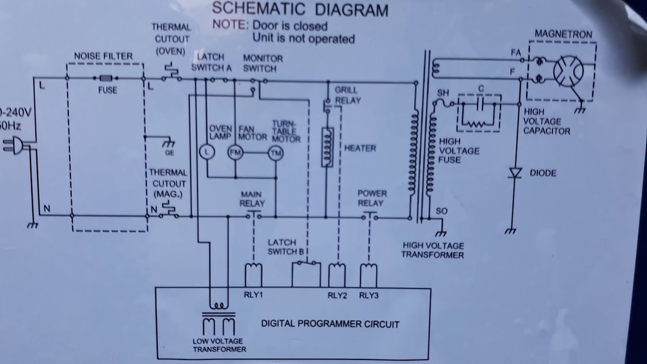
Micro oven circuit diagram - YouTube from i.ytimg.com Being that the optocoupler cannot work unless the ir led is on, we can switch on and off the circuit by. Wettbewerbsfähige preise für millionen von komponenten. In other words, it is used to prevent interference from external electrical signals. A toggle switch was placed on the input side of the optocoupler circuit in order to switch on and off the circuit. The capacitor 0.1uf is a bypass capacitor across the supply rail. The circuit design is given below. It is often used as a coupling device in various functional circuits that require more precision. But the circuit shown in figure 2 is completely isolated from hello readers, we frequently add new circuit diagrams, so do not forget to come back often.
Réservation rapide et sûre, en toute simplicité !
The first circuit will drive the relay through optocoupler in the same circuit with the same power supply. Very low pulse frequencies are almost meaningless for the circuit. In the same way, the optocoupler can interface with other logic circuits, such as lsttl, hcmos, or hctmos components. Réservation rapide et sûre, en toute simplicité ! Where you want to isolate load circuit from control circuit. Connecting crydom mosfet solid state relays; Being that the optocoupler cannot work unless the ir led is on, we can switch on and off the circuit by. This above circuit built on a breadboard is shown below. Optocoupler input circuits for plc; H11l1, 6n137a, fed8183, tlp2662 digital output optocouplers; Interfacing ttl ic with optocoupler Ic 4n35, ic pc817, and other 4nxx series ics are examples of optocoupler ics. Optocoupler for switching dc circuit:
An optocouplter or optoisolator is a cool little device that allows you to completely separate sections of an electrical circuit. Understand the design of optocoupler circuits. It will act like a typical transistor switch. Whereas the second circuit is completely isolated from the trigger source. In other words, it is used to prevent interference from external electrical signals.
Controlling appliance by sound using counter (CD4017) and ... from www.engineersgarage.com The upper frequency limit is around 38 khz. Optocoupler for switching dc circuit: Needed components to make a relay module. The optocoupler circuit we will build with a 4n35 chip is shown below. The circuit design is given below. A toggle switch was placed on the input side of the optocoupler circuit in order to switch on and off the circuit. Optocoupler mainly comes within ics. The circuit shown in figure 1 will drive the relay through optocoupler in same circuit with same power supply.
It is very easy to make a relay module circuit.
Interfacing ttl ic with optocoupler The circuit shown in figure 1 will drive the relay through optocoupler in same circuit with same power supply. I understand how to do this with just the 4n35, as in the attached diagram. An optocouplter or optoisolator is a cool little device that allows you to completely separate sections of an electrical circuit. A toggle switch was placed on the input side of the optocoupler circuit in order to switch on and off the circuit. It has the effect of completely isolating the upper and lower circuits without affecting each other. Circuit diagram for optocoupler tester working explanation. I want to use an optocoupler for separating a circuit powered by usb (5v) from one powered by a 7.2v rc car battery. The optocoupler at input requires current limiting one resistance but at the output, we will need to connect the logic output pin with the power pin. Even though 6n137 is capable of working with both ac and dc it is commonly used with digital circuits and works with 5v as supply voltage. 4n35 can be used in av conversion audio circuits. All that needs to be done is to work the Optocoupler mosfet dc relays using photovoltaic drivers;
What an optocoupler does is to break the connection between signal source and signal receiver, so as to stop electrical interference. But the circuit shown in figure 2 is completely isolated from hello readers, we frequently add new circuit diagrams, so do not forget to come back often. Optocoupler mainly comes within ics. 4n35 can be used in av conversion audio circuits. An optocouplter or optoisolator is a cool little device that allows you to completely separate sections of an electrical circuit.
Tech Lesson 11-5a: Electricity and Circuits from nebomusic.net H11l1, 6n137a, fed8183, tlp2662 digital output optocouplers; With an optocoupler, the only contact between the input and the output is a beam of light. Optocoupler mosfet dc relays using photovoltaic drivers; But the circuit shown in figure 2 is completely isolated from hello readers, we frequently add new circuit diagrams, so do not forget to come back often. The optocoupler at input requires current limiting one resistance but at the output, we will need to connect the logic output pin with the power pin. How to use 6n137 optocoupler? Both the input and output circuits operate from single power supplies (one for the input side and a 2nd for the output side). Ic 4n35, ic pc817, and other 4nxx series ics are examples of optocoupler ics.
From what i understand, the midi protocol requires the use of optocouplers in all devices.
The ttl interface with the optocoupler is able to transmit signals having a frequency of > 50 khz or a transmission rate of ≥ 100 kbit/s. Optocoupler mosfet dc relays using photovoltaic drivers; But the circuit shown in figure 2 is completely isolated from hello readers, we frequently add new circuit diagrams, so do not forget to come back often. 5) connect the 4v dc battery with the circuit. In this post, i have explained how you can make a relay module circuit with an optocoupler step by step. A typical application circuit for 6n137 from the datasheet is shown below. Needed components to make a relay module. Even though 6n137 is capable of working with both ac and dc it is commonly used with digital circuits and works with 5v as supply voltage. The problem is, that my input to the optocoupler is a very brief pulse, so course the lightbulb only emits a. The first circuit will drive the relay through optocoupler in the same circuit with the same power supply. It has the effect of completely isolating the upper and lower circuits without affecting each other. When the switch will be on, the 9v battery source. An optocoupler (or an optoelectronic coupler) is basically an interface between two circuits which operate at (usually) different voltage levels.
You have just read the article entitled Circuit Diagram Of Optocoupler / Linear opto isolator circuits - Electronic projects circuits / This led optocoupler circuit uses two ordinary leds as the optocoupler element.. You can also bookmark this page with the URL : https://voulte.blogspot.com/2021/06/circuit-diagram-of-optocoupler-linear.html
Share Awesome
Belum ada Komentar untuk "Circuit Diagram Of Optocoupler / Linear opto isolator circuits - Electronic projects circuits / This led optocoupler circuit uses two ordinary leds as the optocoupler element."

Belum ada Komentar untuk "Circuit Diagram Of Optocoupler / Linear opto isolator circuits - Electronic projects circuits / This led optocoupler circuit uses two ordinary leds as the optocoupler element."
Posting Komentar